
Please read: I'll gladly answer questions regarding software that I've written, but I cannot help with homework, class assignments, projects and unrelated AVR programming questions. Thanks.
Current version is: 2313Temp820090402.zip
Code Updated: Apr. 02, 2009 Fixed a bug that caused a 0.5C error for some temperature values.
Overview
One way to learn a new processor's architecture and assembly language is to port a well understood program from a different architecture.
I decided that I'd learn how to AVRs by porting LCDTemper8, my MC68HC11 assembly language program to read multiple DS18S20s. The result is 2313Temper8 for the Atmel AT90S2313-10.
One unforeseen side benefit of this approach was finding and correcting bugs in the original code, and finding a new way of calculating the DS18S20's extended temperature.
2313Temper8demonstrates:
- Extracting the 64 bit ROM ID for up to 8 DS1820/DS18S20 devices and calculating the extended temperature for each device
- Simple interrupt driven serial I/O
The program starts by resetting the DS 18S20 bus and reading the 64 bit ROM ID for each device. When a character is received by the UART, it causes an interrupt and is promptly read by the software.
There are only three commands:
R (upper or lower case) sends the number of devices and their ROM IDs via the UART.
T (upper or lower case)followed by a number from 0 through 7 returns the extended temperature for that device, followed by a CR and LF.
V (upper or lower case)followed by a number from 0 through 7 returns a verbose listing for the device by sending the register contents and calculating the extended temperature for that device, followed by a CR and LF.
r <- character sent to program

4
0800080007CC0010
C000080007728A10
0D00080007455E10
3300080007B60510

0000000000000000
0000000000000000
0000000000000000
0000000000000000


t0
+025.25C

t1
+023.57C

t2
+023.82C

t3

+022.94C

v0
3300A199FFFF0810C4
+25.25C
Hardware
2313Temper8 was tested on an Atmel AT90S2313-10 running at 10MHz, using a ceramic resonator. The program was developed in Atmel's AVR Studio 4 and the
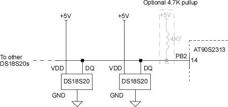
STK500 development board. The program's hardware requirements are minimal; only one bit - Port B bit 2 (PB2), one hardware timer and the UART are used.
The Dallas 1-Wire bus requires a pull-up to +5V. Typically, a single 4.7K Ohm resistor on the DS18S20 DQ line (PB2 in this case) is all that's required. In my code, I've turned on the pull-up feature of the AVR's ports; this is enough for the 1-Wire bus and eliminates the need for the external 4.7K pull-up resistor. I've tested this method with up to four DS18S20s, and they operate flawlessly. I also tested the same code with an external 4.7K pull-up and it works as well.
Either the internal port bit pull-up or an external 4.7K resistor can be used with this program, but regardless of the method used the DS18S20s won't work properly without a pull-up!
Code description
2313Temper8
starts by initializing the AVR stack, 1-Wire data line (PB2)and UART before doing a ROM search on the 1-Wire bus.
Most of the program was translated directly from the 68HC11 code, so I didn't have to write much from scratch. The original 68HC11 ROM search routines took some effort to write; luckily, the Dallas/Maxim 1-Wire software development download page has a Public Domain assembly language example for the Motorola 6805 called ML6805. It includes a ROM ID search routine that I converted to 68HC11 assembly language; it's called ROM1st in both versions. I didn't do much to optimize the code for either the 68HC11 or the AVR... I just made it work. Optimization - as my calculus books used to say - is left as an exercise for the reader.
This routine extracts one device ID from the bus, and indicates if this is the only device on the bus or if other devices were found. It also returns a failure if no devices are found.
I used the C code in the Dallas/Maxim Application Note 162: INTERFACING THE DS18X20/DS1822 1-WIRE TEMPERATURE SENSOR IN A MICRO-CONTROLLER ENVIRONMENT as a guide to writing the GetROMS routine.
GetROMS calls the ROM1st routine up to 8 times. Each time a ROM ID is found the 8 ID bytes are copied to one of 8 locations allocated in RAM for ROM ID storage. The routine then calls ShowROM. This routine steps through the 8 device ID locations in RAM and converts them to ASCII hex before sending them out the serial port. Empty locations (where no devices were found) are shown as 00000000.
The 68HC11 ShowROM routine has a bug (or feature) that causes it to list the ROM IDs in reverse order. Since the program puts the IDs codes onto the ROM bus in the correct order, it's not a big deal. In any case, the AVR version shows the IDs in the order presented in the Dallas data sheet for the DS18S20.
The program's main loop is pretty simple - it just waits until incoming data causes a UART interrupt. I should probably put the AVR in SLEEP mode to conserve power; maybe in a later version.
Any character received at the serial port will case an interrupt. The serial I/O interrupt handler first disables all further interrupts, then parses (in ParseIn) the incoming character for commands that it recognizes (only R, Tn and Vn, where n is a number from 0 to 7). I used an interrupt routine to provide a quicker response to incoming data. After the commands have been processed, the interrupts are re-enabled and the program picks up where it left off.
When a valid command to read the temperature is received by the UART, the program reads the device temperature, then does an extended temperature calculation before sending the temperature (as ASCII) out the UART. If the V (Verbose) command is received, the program sends the register contents of the selected device (as ASCII hex) before sending the extended temperature results.
The DS18S20's TempMSB and TempLSB registers only provide a basic temperature reading, limited to +/- 0.5 degrees C.
The DS18x20 has a way of extending the resolution to about +/- 0.1 degrees C (actually, 1/16 C or 0.0625C)
Calculating this extended temperature accurately in assembly language is harder than it seems. Part of the problem has been the unclear (at least to me) description in the datasheet.
The DS18s20 data sheet gives the equation for calculating the extended temperature:
1) Extended Temperature = Temperature_read - 0.25 + ((count_per_c - Count_remain)/count_per_c)
Temperature_read is calculated by shifting the contents of the TempLSB to the right by 1 (or dividing by two) to eliminate the 0.5C bit. The values found in the Counts_Remaining and Counts_per_C registers are used to extend the temperature resolution.
In the DS18S20, count_per_c is always 16, (double check this value in the data sheet, just in case it has changed for a new device!)
so this allows us to simplify the equation:
2) Extended Temperature = Temperature_read - 0.25 + ((16 - Count_remain)/16)
Unfortunately the '2313 lacks both a floating point unit and the program space required for an extensive floating point library, so this equation has to be boiled down into a form that can be easily handled by the instructions available.
First, multiply everything by 16:
3) 16 * Extended Temperature = 16 * Temperature_read - 16 * 0.25 + 16* ((16 - Count_remain)/16)
This simplifies to:
4) 16 * Extended Temperature = 16 * Temperature_read - 4 + 16 - Count_remain
5) 16 * Extended Temperature = 16 * Temperature_read + 12 - Count_remain
In the code, the TempLSB value (as read from the device) is shifted right by 1 to truncate the 0.5C bit then multiplied by 16.
6) 16 * TempLSB + 12 - Count_remain
To get the extended temperature, we would divide this number by 16... and we would end up with a fixed point value. Still no good.
If we multiply step 6 above by 100, then divide by 16, we would end up with a 16 bit integer, which is what we want. Multiplying by 100 and then dividing by 16 can be simplified to multiplying by 25 and dividing by 4:
7) Extended Temperature = (((16 * TempLSB) + 12 - Count_remain)*25)/4
Converting this 16 bit integer to an ASCII string is straightforward.
(Thanks to Stephan Stadler for pointing out an arithmetic error that was producing incorrect temperature readings, and to Michael Minns for pointing out a bug that was not always eliminating the 0.5C bit)
We can verify this formula with real register data from a DS18S20:
The first byte above, 0x36 is TempLSB. The decimal value is 54
Count_Remaining is 0x0F, or 15
First, shift TempLSB right by one bit = 0x1B (27 decimal)
Next, plug in the values into the formula:
Extended Temperature = ((16 * 0x1B + 0x0C - 0x0F)*0x19)/4
Extended Temperature = ((16 * 27 + 12 - 15)*25)/4
This is a positive temperature. We put a decimal point between the most and least significant bytes of the result and we get an extended temperature of:
This result can be verified by using the Datasheet formula:
27 - 0.25 + ((16-15)/16) = 26.8125, which is close enough to 26.81 for government work; the difference is due to rounding errors when doing integer arithmetic.
We can run the numbers from the DS18S20 datasheet table 2 to see if we get the same results:
Since count_per_c is fixed at 16, the smallest change in temperature that the DS18S20 can detect is 1/16° C, or 0.0625° C; it's obvious that the DS18S20 is not accurate to 0.01° C. In reality, it's probably not even accurate to 1/16° C. You should round the returned temperature to 0.1° C in the host program on the PC.
Most of the program was translated directly from the 68HC11 code, so I didn't have to write much from scratch. The original 68HC11 ROM search routines took some effort to write; luckily, the Dallas/Maxim 1-Wire software development download page has a Public Domain assembly language example for the Motorola 6805 called ML6805. It includes a ROM ID search routine that I converted to 68HC11 assembly language; it's called ROM1st in both versions. I didn't do much to optimize the code for either the 68HC11 or the AVR... I just made it work. Optimization - as my calculus books used to say - is left as an exercise for the reader.
This routine extracts one device ID from the bus, and indicates if this is the only device on the bus or if other devices were found. It also returns a failure if no devices are found.
I used the C code in the Dallas/Maxim Application Note 162: INTERFACING THE DS18X20/DS1822 1-WIRE TEMPERATURE SENSOR IN A MICRO-CONTROLLER ENVIRONMENT as a guide to writing the GetROMS routine.
GetROMS calls the ROM1st routine up to 8 times. Each time a ROM ID is found the 8 ID bytes are copied to one of 8 locations allocated in RAM for ROM ID storage. The routine then calls ShowROM. This routine steps through the 8 device ID locations in RAM and converts them to ASCII hex before sending them out the serial port. Empty locations (where no devices were found) are shown as 00000000.
The 68HC11 ShowROM routine has a bug (or feature) that causes it to list the ROM IDs in reverse order. Since the program puts the IDs codes onto the ROM bus in the correct order, it's not a big deal. In any case, the AVR version shows the IDs in the order presented in the Dallas data sheet for the DS18S20.
The program's main loop is pretty simple - it just waits until incoming data causes a UART interrupt. I should probably put the AVR in SLEEP mode to conserve power; maybe in a later version.
Any character received at the serial port will case an interrupt. The serial I/O interrupt handler first disables all further interrupts, then parses (in ParseIn) the incoming character for commands that it recognizes (only R, Tn and Vn, where n is a number from 0 to 7). I used an interrupt routine to provide a quicker response to incoming data. After the commands have been processed, the interrupts are re-enabled and the program picks up where it left off.
When a valid command to read the temperature is received by the UART, the program reads the device temperature, then does an extended temperature calculation before sending the temperature (as ASCII) out the UART. If the V (Verbose) command is received, the program sends the register contents of the selected device (as ASCII hex) before sending the extended temperature results.
The DS18S20's TempMSB and TempLSB registers only provide a basic temperature reading, limited to +/- 0.5 degrees C.
The DS18x20 has a way of extending the resolution to about +/- 0.1 degrees C (actually, 1/16 C or 0.0625C)
Calculating this extended temperature accurately in assembly language is harder than it seems. Part of the problem has been the unclear (at least to me) description in the datasheet.
The DS18s20 data sheet gives the equation for calculating the extended temperature:
1) Extended Temperature = Temperature_read - 0.25 + ((count_per_c - Count_remain)/count_per_c)
Temperature_read is calculated by shifting the contents of the TempLSB to the right by 1 (or dividing by two) to eliminate the 0.5C bit. The values found in the Counts_Remaining and Counts_per_C registers are used to extend the temperature resolution.
In the DS18S20, count_per_c is always 16, (double check this value in the data sheet, just in case it has changed for a new device!)
so this allows us to simplify the equation:
2) Extended Temperature = Temperature_read - 0.25 + ((16 - Count_remain)/16)
Unfortunately the '2313 lacks both a floating point unit and the program space required for an extensive floating point library, so this equation has to be boiled down into a form that can be easily handled by the instructions available.
First, multiply everything by 16:
3) 16 * Extended Temperature = 16 * Temperature_read - 16 * 0.25 + 16* ((16 - Count_remain)/16)
This simplifies to:
4) 16 * Extended Temperature = 16 * Temperature_read - 4 + 16 - Count_remain
5) 16 * Extended Temperature = 16 * Temperature_read + 12 - Count_remain
In the code, the TempLSB value (as read from the device) is shifted right by 1 to truncate the 0.5C bit then multiplied by 16.
6) 16 * TempLSB + 12 - Count_remain
To get the extended temperature, we would divide this number by 16... and we would end up with a fixed point value. Still no good.
If we multiply step 6 above by 100, then divide by 16, we would end up with a 16 bit integer, which is what we want. Multiplying by 100 and then dividing by 16 can be simplified to multiplying by 25 and dividing by 4:
7) Extended Temperature = (((16 * TempLSB) + 12 - Count_remain)*25)/4
Converting this 16 bit integer to an ASCII string is straightforward.
(Thanks to Stephan Stadler for pointing out an arithmetic error that was producing incorrect temperature readings, and to Michael Minns for pointing out a bug that was not always eliminating the 0.5C bit)
We can verify this formula with real register data from a DS18S20:
36004B46FFFF0F102B
The first byte above, 0x36 is TempLSB. The decimal value is 54
Count_Remaining is 0x0F, or 15
First, shift TempLSB right by one bit = 0x1B (27 decimal)
Next, plug in the values into the formula:
Extended Temperature = ((16 * 0x1B + 0x0C - 0x0F)*0x19)/4
Extended Temperature = ((16 * 27 + 12 - 15)*25)/4
16 *27 = 432

   +12 = 444

  - 15 = 429

   *25 = 10725

    /4 = 2681
This is a positive temperature. We put a decimal point between the most and least significant bytes of the result and we get an extended temperature of:
+26.81C
This result can be verified by using the Datasheet formula:
27 - 0.25 + ((16-15)/16) = 26.8125, which is close enough to 26.81 for government work; the difference is due to rounding errors when doing integer arithmetic.
We can run the numbers from the DS18S20 datasheet table 2 to see if we get the same results:
TEMPERATURE/DATA RELATIONSHIP

+85.0°C 00AAh

+25.0°C 0032h

 +0.5°C 0001h

    0°C 0000h

 -0.5°C FFFFh

-25.0°C FFCEh

-55.0°C FF92h
If you assume that Count_Remaining is 0x0C (12) the
equation in
step 7
gives us the same results as the table. Note that
for negative temperatures you have to take the 2's complement of the
TempLSB
value. In the code, TempMSB is used to decide if the temperature is
negative. If it is, I take the 2's complement of the TempLSB and
store
it back to TempLSB. I leave TempMSB
untouched, since it's used several times in the code to determine if
the temperature is negative.. Since count_per_c is fixed at 16, the smallest change in temperature that the DS18S20 can detect is 1/16° C, or 0.0625° C; it's obvious that the DS18S20 is not accurate to 0.01° C. In reality, it's probably not even accurate to 1/16° C. You should round the returned temperature to 0.1° C in the host program on the PC.
Comments
Having a 1-Wire ROM search routine is useful if you can only spare one bidirectional pin in your design, or if you need
to use more DS18S20s than you have bidirectional pins available. Otherwise, please consider other options that may be easier to
implement. One way is to use one bidirectional I/O pin per DS18x20. This would allow you to dispense with the ROM search and ROM matching
routines and would match a port bit/DS18x20 with a particular location.
With my code, all you get is a list of ROM ID numbers, not the physical location of the device. For instance, assume that device 0 is an
outdoor temperature device and Device 1 is measuring the indoor temperature. If you replace the outdoor device with a new DS18x20, it may no longer
appear as device 0 in the ROM list if its ROM ID number is higher than Device 1...which may now become Device 0.
You can also skip the extended temperature calculations if you use a DS18B20, which provides up to 12 bits of temperature data.
Why don't I display the temperature in degrees F? I just couldn't be bothered to write the code! Also note the almost total lack of error checking in the routines; for example, the software reads the DS18S20's CRC byte, but it's not used at all. I was going to write a table based CRC routine (there are several examples on the 'net and in the Dallas app notes) but my 68HC11 hardware - with a DS1820 at the end of an 8 meter cable - worked continuously, without error for over a year. This isn't production code, just "experimenter's" code; you may want to add the CRC error check if accurate, trusted data is critical for your project.
I used the Atmel STK500 development kit (PDF) on this project. It was only $79 from Digikey. The STK500 comes with an excellent assembler/debugger IDE, and supports a wide range of AVR devices and programming modes. The code was originally developed on the AT90S8515 that comes with the STK500. Porting the code to the '2313 took less than 15 minutes - including the time required to remove the '8515 and insert the '2313 into the STK500 socket.
Download 2313Temper8