The UCLA Astronomy Department operates a 24" Cassegrain telescope on the roof of the Math Sciences Annex building, on the UCLA campus.
The UCLA 24-in Telescope and a Dual Optical-IR Imaging System Publications of the Astronomical Society of the Pacific 109: 600-608, 1997 May

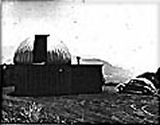
The 24"at Ojai
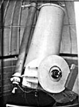
The UCLA 24" telescope is one of at least two identical telescopes built at Cal Tech in 1964.
One telescope was placed on Mt. Wilson, where it is now being used for remote observing.
The UCLA telescope was placed on a hilltop site in Ojai, California.

The 24" served the Department until 1981, when the owners of the Ojai property asked the University to remove the telescope.

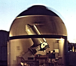
The 24" in the UCLA dome.
The "transparent" effect was archived by opening the dome shutter and doors, turning on the lights and letting the dome rotate roughly 180 degrees. This film exposure was about 30 seconds long.

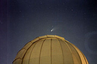
A picture of comet Hale-Bopp above the UCLA dome.
This picture was taken in May, 1997; the original print shows the Pleiades on the left edge of the frame. The ring to the right of the dome is courtesy of the film developers.
In late 1981, the 24" was moved to the UCLA campus. A crane raised it
onto the roof of the Math Sciences Annex building and into an existing dome that had been
modified to receive the telescope. Plans had been made to bring the
telescope back into operation, but instead it languished in its cramped
dome for six years.
In 1987, Nick Magnone, Chris Shelton and I (Frank Henriquez) were
asked to repair and prepare the telescope for a graduate Observational
Astronomy class.
We got the telescope to work well enough for the graduate class, but
only after extraordinary effort. It didn't take us long to realize that
while the telescope's mirrors were in good shape, the drive electronics
and large AC motors were no longer adequate for the task of slewing and
tracking the telescope.
Between 1987 and 1993, Nick and I removed all of the old electronics
and AC motors (more than 400 lbs. worth), recast new counterweights
from lead, refurbished the mechanical parts of the telescope and dome and
realuminized the mirrors.
The telescope's original drive electronics were a complicated and
dangerous mess of circuit boards, wires and motors. The boards, cables,
AC motors and planetary gear reducers on the RA and Dec axis were
stripped out and replaced by a far more compact design. With the help
of Brant Nelson, who at the time was an Astronomy department graduate
student, new instruments and control software were added and the
telescope (in its new configuration) saw first light in July, 1993. It
was used extensively until January 17, 1994.
During our tests of the telescope between June and December of 1993,
Brant and I noticed that images taken to the extreme East or West
(around ± 3.5 hours in RA from the Meridian) were often
trailed
in both RA and Dec... as if the telescope had been jarred during the
exposure. We were puzzled by this, and could only guess that the image
distortion was caused by an improperly balanced telescope. The
imbalance
would cause it to seize briefly at the extreme RA positions. We had
other pressing challenges, so we shrugged this minor problem off as
something to deal with at a later date.
On the morning of January 17, 1994 a very strong earthquake shook Los
Angeles and many buildings on the UCLA campus (including ours) were
extensively damaged. The earthquake caused the telescope domes (which
include the walls and doors) to jump off their tracks. The motion was
severe enough to pop the rivets holding down the dome's exterior sheet
metal panels.
We were expecting to see a disaster inside the dome, but were surprised
to find that everything was still in place. One monitor fell to the
floor, but was undamaged.
But not all was as it seemed.
Days later, after Nick put the telescope's dome back into operation,
Brant and I discovered that the telescope could no longer track
properly. Obviously, the earthquake had undone our polar axis
alignment,
so we set out to realign it. To our dismay, we discovered that the
telescope's pedestal adjustments no longer had the range necessary to
realign the polar axis; either the telescope or the building had
shifted
in the earthquake.
With Nick's help, we removed the floor tiles and aluminum floor panels
and examined the telescope's supports. The 24" is bolted to a polygonal
steel riser that connects the telescope pedestal to a massive
vibration-isolated concrete block that serves as a telescope pier.
According to the architectural plans of the 1981 move from Ojai, the
riser had been bolted to the large concrete platform that covered the
pier.
We were all surprised to see how easy it was for Nick to push the
telescope around with a steel pipe and some leverage. In horror, we
slowly realized that the
telescope was not bolted to the pier!
The riser was indeed firmly bolted to the concrete platform...but the
"concrete platform" itself was nothing more than a very large tin "pie
pan" filled with cement. This pie pan appears in the 1950's vintage
building plans as an extension of the concrete pier...but in reality
was nothing more than a weather flashing to protect the pier itself
from
the elements during the building's construction. The concrete platform
was not bolted down or held in place by anything other than its
weight...and the weight of the telescope bolted to it. It had been like
this for 13 years! The force of the earthquake had shattered the
concrete, jarred the pie pan loose and twisted the telescope so that
the
polar axis was now pointing slightly to the East and South.
The earthquake had at least solved one puzzle - we finally had an
explanation for the jarred images that Brant and I had seen
earlier...the telescope, at its extreme RA positions had been causing
the pie pan to tip and tilt slightly (by a few arc seconds!)
It took us a while to convince the campus engineers that their building
drawings did not conform to reality, and a while longer to formulate a
repair plan.
The campus engineers decided to remove the crushed weather flashing and
to bolt the telescope riser directly to the concrete block - as it
should have been done back in 1981. Of course, this meant lifting the
telescope! We had to remove the mirrors and drive electronics, leaving
only the tube, fork mount and gears, pedestal and riser. After we had
removed all the delicate bits, the construction company built a massive
steel framework inside
the dome. Using chains, they hoisted the
telescope into the air.
After several months of work, they had placed massive steel bolts deep
into the concrete block, and Nick and I carefully aligned the riser to
the meridian. The polar axis adjustment on the 24" has a very narrow
range, so it was critical to get the riser in just right.
I had used the long hiatus to clean the telescope optics, so by June of
1994, we were able to put the telescope back into operation. After
spending several nights aligning the telescope to the Polar Axis, we
noticed that stars still left a small trail in Right Ascension,
regardless of the integration time. This pointed to a problem with the
telescope drive system. After some detective work, I discovered that
the
telescope was vibrating at a very low frequency. Just our luck! The 24"
had a resonance near the undivided RA tracking rate (41.8
steps/second).
We fixed this problem by placing the RA stepper motor on rubber
vibration isolators and adding a flexible coupler between the stepper
motor and the gear reducer.
A final legacy of the '94 quake was a strange tracking error right at
the meridian. On inspection, we noticed that the large brass RA gear
had
been damaged during the earthquake. The intense shaking had caused the
gear to vibrate rapidly against the steel worm, badly gouging two teeth
on the gear. The solution was to rotate the gear 90 degrees so that the
damaged teeth were beyond the normal range of telescope motion. Nick
also added a thick steel bar that locks the telescope into place when
not in use, but swings out of the way during normal telescope
operation.
This bar will eliminate any damage to the gear during future
earthquakes.
Brant Nelson used the UCLA 24" telescope to gather most of the data for
his Ph.D, thus making him the first graduate student to do so since the
telescope was moved to UCLA.
The 24" is currently being used by several
graduate students and groups in support of their research projects.
The 24" is a Cassegrain type all reflective
telescope, with a 24" clear aperture f3.5 paraboloid primary and a 6"
diameter hyperboloid secondary. The effective focal length is 384.1"
(f/16.0). The telescope carries two permanent instruments:
A CCD
camera (not shown) equipped with B V R I and clear filters at the
Cassegrain focus.
Kcam-III
- A
2.2u Infrared Camera is mounted on the East Dec axis port.
Kcam uses a cryogenically cooled
256 x 256 pixel Rockwell NICMOS III HgCdTe detector. A 2.2µ
filter
inside the dewar limits Kcam to the K band and gives it its name. A
dichroic mirror in the return optical path from the Cassegrain
secondary
reflects light above 0.9 microns to Kcam while allowing most of the
light below 0.9 microns to pass through to the Cass focus and the CCD.
On the 24", Kcam has a plate scale of about 0.85"/pixel.
KCam-III has been modified and a motorized filter wheel and new optics
have been added by James
Larkin,
Ph.D. The modified KCam has been
used at Keck. When away, KCam's place is taken up by a counterweight
and RockCam...a
cardboard box full of pebbles that approximates the weight of KCam and
its electronics.
Cleaning the optics of this telescope presented some challenges. While the 6" secondary - protected
by its long baffle tube - was very clean, the primary was a different
story. Even though the telescope tube has a dust cover, the earthquake
and the extensive campus repairs and construction that followed had
coated the primary with a thick layer of dust. One of my major concerns
had been the sandblasting work done on Powell Library; I could see
clouds of fine dust drifting towards our building, and on close
inspection, I could see that some of it had managed to land on the
primary.
Cleaning the primary by washing it was clearly out; not only would
handling a wet, 300lb Pyrex mirror present some interesting challenges,
I could just picture those sharp edged sand grains leaving long
scratches in the aluminum coating as they washed off.
I contacted Thomas Waineo, a retired master
optician (now
deceased) on CompuServe, and he was kind enough to send me a small jar
of 3M Strippable Coating. The 3M liquid is no longer available, but
it's
essentially Collodion.
I taped a strip of paper around the outer edge of the primary and
another along the edge of the central perforation, and slowly poured
the
3M Strippable coating evenly over the surface. I used a very clean
camel
hair brush to distribute the viscous liquid, taking care not to touch
the surface of the mirror with the brush hairs. The only difficulty I
encountered was the smell of the solvent as it evaporated from the
coating. This is a job that must be done in a well
ventilated
room, away from open flames, sparks and other localized heat sources!
By the next day, the 3M Strippable Coating had dried into a clear
flexible skin. I used some masking tape to peel the skin off of the
mirror. The results were amazing; I ended up with a translucent donut
of
dried coating and a very
clean mirror. The coating felt like 400
- 600 grade sandpaper, and you could see all the grit and dust trapped
in the coating.
The strippable coating didn't get rid of all the dirt and oils, but
what was left was easily taken care of by rinsing the mirror with
isopropyl alcohol followed by several rinses with distilled water and
blotting dry with very clean, lint free cotton rags. I let the water
drain through the central hole and into a bucket under the mirror cell.
The mirror was left dust and oil free, with no new scratches or damage
to the coating.
This Google search for collodion mirror cleaning
should provide enough links on how to use collodion to clean mirrors, and where to buy it.
The AC motors and drive electronics were replaced by two small stepper
motors and 5:1 gear reducers. Each stepper motor was originally driven
by a 10 microstep/step driver from Oregon Microsystems (OMS). Before
leaving Astronomy, I replaced the original drivers with IMS
(Intelligent Motion Systems) 804
microsteppingdrivers. The new drivers are smaller, more efficient and
allow greater microstepping ratios, down to 256 microsteps per step.
The
new drivers will allow us to use a higher microstepping ratio during
tracking, which should eliminate all the vibrations caused by the RA
stepper motor. Since the microstepping ratio can be changed on the fly,
it can be increased during slewing. The microstepping drivers are in
turn controlled by two Cybernetic
Micro Systems CY545 stepper
motor controller ICs. The CY545s
do the
acceleration/deceleration ramps and an Intel 8254 Programmable Timer
handles the RA tracking rate. The CY545s, Motorola MC 6821 parallel
port, Intel I8254 programmable timer, control PAL (Programmable Array Logic) , address decoding and
bus buffering ICs are built on a small 8 bit PC expansion card and
placed in an old Leading Edge PC. The schematics and parts list are
available on request.
Since the acceleration ramps required for slewing are handled by the
CY545s, the telescope control software (written in Turbo Pascal) is
greatly simplified. Tracking is done by the Intel 8254 timer, which
acts
as a free running oscillator at the selected tracking rate. A PAL is
used to select between tracking and slewing, directing the appropriate
step pulses to the RA driver.
Most of the software, which has grown and been
modified as we gain
experience with the telescope, is concerned with keeping track of time
and the telescope's position. I wrote the CY545 control code and the
rudimentary beginnings of the telescope control and pointing program,
but much of the remaining code was written by and with the help of
Brant Nelson, who received his Ph.D in 1997.